At last version 4 (probably more like version 44) of my wireless controller is done so Id like to take the opportunity to share it with the group.
Development has ended up with much smaller units which are still mostly prototype rather more than production standard in as much as I can disassemble them (the hand controller is one part and the powerbase is the other) to try out ideas and so on. A previous version showed me that using a custom PCB was easier to build and potentially smaller but a nightmare to rework should the need arise.
A major change is this hand controller doesnt have a load of potentiometers on it to adjust the settings. The new version has a single encoder and a push button and the settings are read of a small OLED screen. Whilst individual controls for each setting are effective the approach doesnt allow for new settings controls to be added easily. The encoder/menu approach allows me to extend the number of settings by adjusting the software. Also the potentiometers have a tendency to wander in their setting a bit whereas the encoder approach is totally precise.
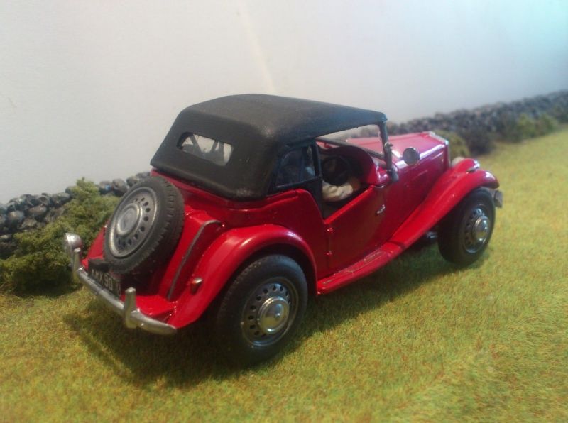
The hand controller uses a Scalextric digital controller for its input. It is mostly standard and I have chosen this as replacements are cheap and available and work pretty well but I have modified a number of commercial controllers. The modifications made are a 2.1mm plug which I use across all my projects, a softer spring in the handle and I built up the button to provide a larger area to press on.
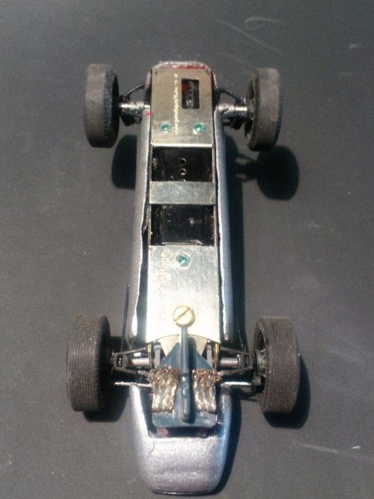
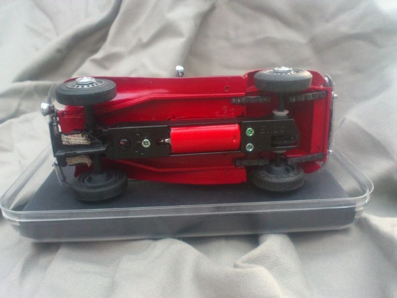
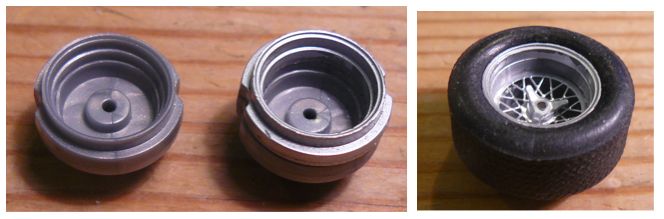
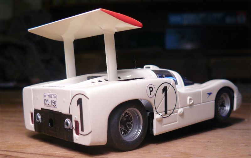
Here is the powerbase. It plugs into the 3pin and has very little to do except adjust the power and braking using PWM outputs in accordance with what the hand controller is set to and sends. A small OLED screen is used just for verification of what is going on during development. This version used an IR control to make various settings including binding the powerbase with the hand controller but this has now been updated with a new method and the IR will be ditched in the future. It is powered by the track supply usually but a battery can be plugged in where your track is unpowered until the start flag drops. A USB port is used for external power and for uploading new software or connecting to a PC for monitoring purposes.
![]()
![]()
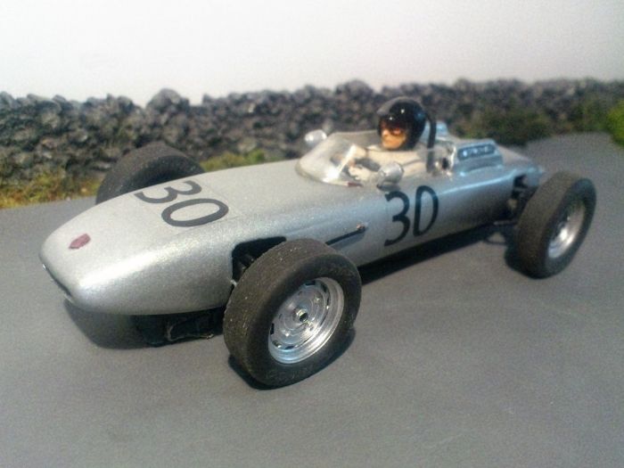
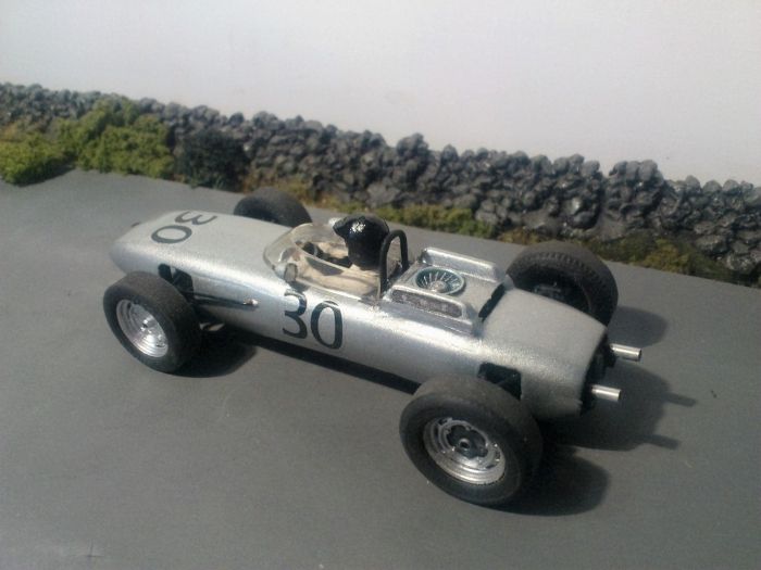
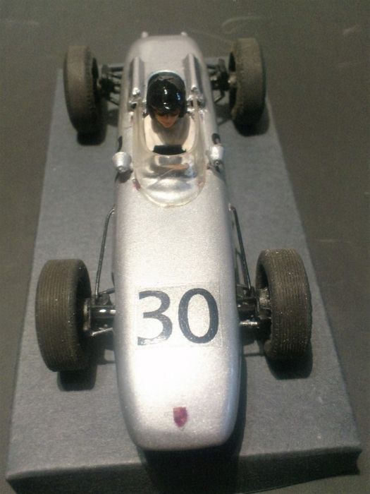
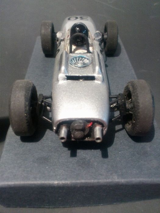
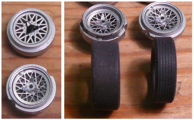
Here is the new hand controller. It has a USB for development and another for battery charging, on/off switch, status LEDs and the encoder/button/OLED screen for settings. Auto binding with the powerbase requires little user input and the binding code is randomly generated and picked up by the powerbase. This approach stops another controller using the same binding code and a powerbase being confused by wireless signals coming from two controllers.
![]()
![]()
![]()
This is the version that has all the features originally planned operational. I cant say if all the variables that can be set need to on a production version but when experimenting you need to be able to fiddle with everything.
You can adjust the trigger to voltage output mapping. Simplistically a one to one mapping of trigger position show 0-100% in the horizontal axis against a 0-100% voltage is shown below.
![]()
You can control the start voltage which kicks in after the trigger has started to be pressed and also the maximum voltage as seen in the image below.
![]()
The landing hold zones at the maximum end of the trigger position can be set where the trigger change causes no change in voltage output until the last trigger movement.
![]()
Also the curve between the start voltage and landing zone can be adjusted to be more or less aggressive is 27 steps. Shown here
![]()
![]()
Braking can be set from 50% to 100% and this kicks in when the trigger position is zero. There is a setting that will control the time the braking will remain on when in the zero trigger position to allow a car to brake and then coast through the corner.
There is also a pre-braking effect that kicks in as the trigger is released but before it reaches zero. You have control over how much falling trigger movement will cause the pre-braking to kick in, the amount of braking that will be applied and for what time period.
A control can be set to soften the jump in voltage delivered when a trigger is snatched on.
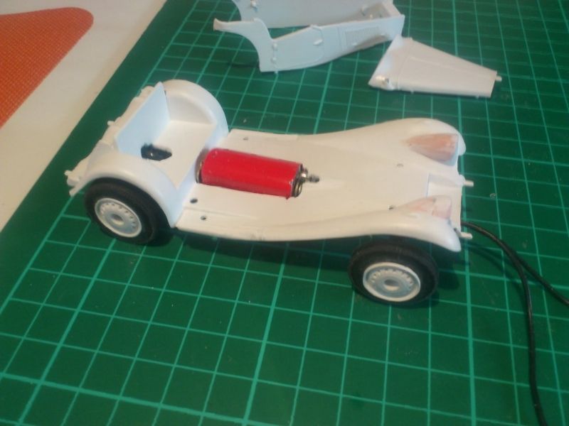
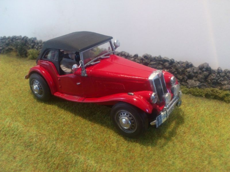
I can also switch on/off debugging information to the PC and control some lights and a siren on a fire safety truck I converted. Whilst it is a bit of fun it was a useful test bed as I put all the powerbase hardware into the truck. This was an experiment to see how robust the wireless connection was in close proximity to a motor and also the wired up brake lights allow me to see when the pre-braking is kicking in even if I cant notice it when driving. It is also serving a pre-cursor to another toy car project.
Now it needs development effort and driving skill (I only have one of those!).


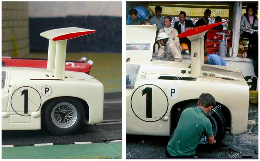


 picture and full field line up --->